Thermoplastic and fiberglass reinforced (FRP) piping is often used for corrosive or corrosive and abrasive fluids. They are generally applied where temperatures range from negative 70-deg F to 300-deg F (negative 57-deg C to 149-deg C). Chemical compatibility becomes a particularly important consideration in these applications, not only for the piping itself but also for the expansion joints. Both must function with the same resistance to attack or problems will arise.
Sealing Sense from FSA
Thermoplastic and fiberglass reinforced (FRP) piping is often used for corrosive or corrosive and abrasive fluids. They are generally applied where temperatures range from negative 70-deg F to 300-deg F (negative 57-deg C to 149-deg C). Chemical compatibility becomes a particularly important consideration in these applications, not only for the piping itself but also for the expansion joints. Both must function with the same resistance to attack or problems will arise.
Thermal and mechanical characteristics differ considerably from those for metal piping. The coefficient of thermal expansion (CTE) is 2X to more than 4X that of steel. The movements and consequent thrust loads that one must deal with are significantly greater.
Another important design consideration is that the strength of these nonmetallic pipes can decrease rapidly with increased temperature.
Thermoplastic vs. FRP
The coefficients of thermal expansion for thermoplastic pipe typically are 3X to 8X that of steel, while that for FRP pipe is roughly 2X that of steel. This results in an expansion joint design that must deal with twice the thermal movement of steel in an unconstrained system. Mechanical considerations also are important. Since FRP is a composite, there are two distinctive axial modulii of elasticity: compression and tensile. The axial compression modulus of elasticity varies from 3 to 10 percent that of steel.
The elastic modulus of the thermoplastic pipe is considerably less than that of either FRP or steel. It also decreases rapidly as the temperature increases above 100-deg F (38-deg C). As a result, very short support spans are required for the thermoplastic pipe at elevated temperatures. Again, this is something the expansion joint design must take into consideration.
Expansion Joint Design
Optimum expansion joint performance requires a determination of the complete range of thermal movements expected in the system.
To do this, a calculation must be made of the maximum thermal expansion and thermal contraction that will be encountered during operation. The expansion joint must be capable of absorbing the full range of thermal movement with an appropriate margin of safety.
Case Study
A Common Cooling Water Project with a capacity 1.32 million-GPM provided the main source of cooling water to a whole industrial complex. It had a network of large diameter FRP piping that distributed the cooling water. Nearly 100 large rubber expansion joints in sizes 60-in (DN 1500) to 144-in (DN 3600) were incorporated throughout the system. Each valve location required a dismantling joint.
The expansion joints were designed to compress 2.375-in (60-mm) on itself, functioning as a dismantling joint, while also accommodating the large thermal movements in the system. These very large parts had to be designed for a test pressure of 200-psi (13.5-bar).
The higher sealing requirement was the primary design focus. The body of the expansion joint was reinforced to handle the high pressure. Since the limitation to previous designs had been leakage at the flange, a review of flange designs was undertaken. It was clear that different flange designs had different advantages and disadvantages. The goal was to take the best features from various designs and develop an optimal design.
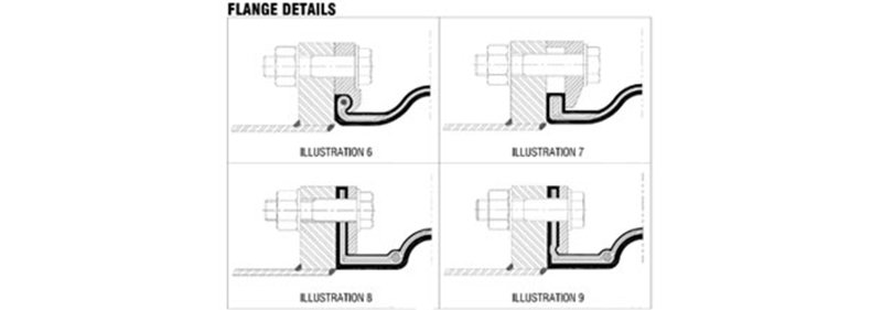
Advantages and disadvantages of the designs shown in Illustrations 6, 7, and 8 of Figure 1 were considered. Analyses resulted in the use of a flange design that incorporated the pressure point feature of the solid floating flange design shown in Illustration 6 with that of the full rubber design of Illustration 8. This new design is shown in Illustration 9 and incorporates a bulb in the retaining ring.
The bulb focuses a sealing force on a relatively small area beneath the bolt circle of the rubber flange. As a result, the bolt torque is minimized and a higher-pressure rating can be achieved. The new design also does not require periodic retorquing of the bolts.
The new design also requires half the bolt torque that the original flat-faced design required for the same test pressure. Pressure ratings that were previously unobtainable are now obtainable. Flange leakage, along with the maintenance-intensive task of periodically retorquing the bolts, was also no longer a concern.
Conclusion
The application of expansion joints to thermoplastic and FRP piping systems requires special attention to design features to ensure optimum long term reliability and safety. Each of the two components must be compatible with the process fluids, which can be particularly aggressive. The large thermal expansions and low strengths of the pipe, as compared with steel, also require incorporation into the system design.
Credit / Source : Pumps & Systems